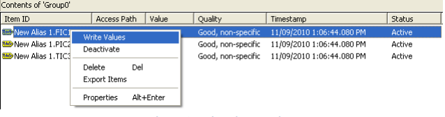
Step 8: Right Click your mouse button on FIC101 and select Write Values.
The BACnet Router provides stand-alone routing between two different BACnet networks such as BACnet/IP, BACnet Ethernet, and BACnet MS/TP – thereby allowing the system integrator to mix BACnet network technologies within a single BACnet internetwork.
| BACNET IP | BACNET MSTP |
|---|---|
| BACnet IP uses a standard UDP/IP stack to send and receive messages. | MSTP stands for Master Slave Token Passing. Each device on the link is considered the “Master” when it has the Token and need to Pass the token along to the next device. |
| BACnet IP describes the way BACnet networks may be formed from group of devices which uses the TCP/IP family of protocols for their communications. | BACnet MSTP is token passing protocol, where in MS stands for Master-Slave and the TP stands for Token Passing. BACnet MSTP is mainly used to connect field devices to controllers/routers/control applications. |
| BACnet IP works over Ethernet Port. | BACnet MSTP works over RS-485 Port. |
| BACnet IP is an Ethernet based Protocol. | BACnet MSTP is a Serial based Protocol. |
| BACNET IP | BACnet MSTP | BACNET MSTP |
|---|---|---|
| BACnet IP uses a standard UDP/IP stack to send and receive messages. | MSTP stands for Master Slave Token Passing. Each device on the link is considered the “Master” when it has the Token and need to Pass the token along to the next device. | A traditional Point-to-Point data link is a communications medium with exactly two endpoints without data or packet formatting. |
| BACnet IP describes the way BACnet networks may be formed from group of devices which uses the TCP/IP family of protocols for their communications. | BACnet MSTP is token passing protocol, where in MS stands for Master-Slave and the TP stands for Token Passing. BACnet MSTP is mainly used to connect field | Peer to Peer is a conventional term and implies that every device converses with every device without |
| devices to controllers/routers/control applications. | the requirement for a server. | |
| BACnet IP works over Ethernet Port. | BACnet MSTP works over RS-485 Port. | BACnet P2P works over RS-232 Port. |
| BACnet IP is an Ethernet based Protocol. | BACnet MSTP is a Serial based Protocol. | It is a Point-to-Point Protocol. |
| MODBUS RTU | Modbus TCP |
|---|---|
| Modbus RTU is Master – Slave Configuration. | Modbus TCP is Client – Server Configuration. |
| In Modbus RTU, there is only one Master Device that communicates over a single loop with multiple slave device. | In Modbus TCP, one or more than one Master Device communicates with single device. |
| It uses different serial physical interfaces (RS485-RS232). | It runs on an Ethernet physical layer. |
| Modbus RTU Supports Checksum. | Modbus TCP does not support Checksum. |
| When compared to Modbus TCP, it is less secured. | When compared to Modbus RTU, it is more secured. |
SNMP V1: It is simpler to set up and just require a plaintext network. But the drawback is that it doesn’t bolster bit counters and has a little security. It bolsters only 32-bit counters.
MP V2CSN: It is a sub-version of SNMP. The main advantage compared to the previous versions is an Inform Command. Traps are simply received by a manager, whereas Informs are positively acknowledged with a response message. If a manager does not reply to Inform, the SNMP Agent will resend the Inform.
SNMP V3: It is the latest version of SNMP and the main feature of it is an enhanced security. Each SNMP entity is uniquely identified in SNMP V3 with the EngineID Identifier. Problems may occur if two SNMP entities have duplicate EngineIDs. The EngineID generates the key for authenticated messages. SNMP V3 security generally comes in two forms, Authentication and Privacy.
| JSON | XML |
|---|---|
| It is Java Script Object Notation and is based on Java Script Language. | It is Extensible Markup Language and is derived from SGML. |
| It supports Array but does not provide any support for namespaces. | It does not support Array but provides support for namespaces. |
| As compared to XML, files are easy to read and interpret. | As compared to JSON, its documents are comparatively difficult to read and interpret. |
| It is less secured and does not use end tags. | It is more secured when compared to JSON and uses start and end tags. |
| It supports only UTF-8 encoding and does not support comments. | It supports various encoding and supports comments. |
MQTT uses the Publisher and Subscriber model to connect interested parties with each other. It does this by separating the sender who is known as the Publisher with the receiver who is called the Subscriber.
The Publisher publishes a message to a main topic that has many Subscribers waiting to receive the message.
The Publisher and Subscriber never meet each other directly. They even aren’t aware about an existence of the other.
Third person who is known as the MQTT Broker is the bridge between Publisher and Subscriber. Broker filters the messages and publishes the incoming messages effectively to the subscribed clients.
No, you do not need any special tool to configure Shubham Gateways. It can be edited with any text editor like Notepad, Notepad++, etc.
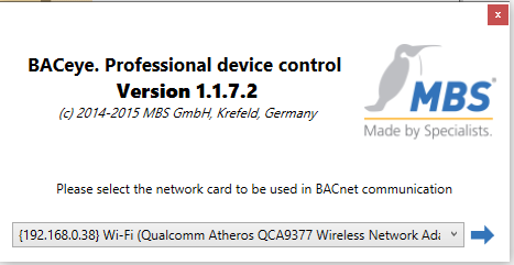
1) Start the BACeye Software and select the Network Adapter from drop down list.
3) On clicking the Properties Tab you can change the Network Adapter and UDP Port as per your requirement and save the settings.
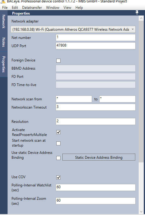
2) On selecting the Network Adapter, it opens the new window of BACeye Software.
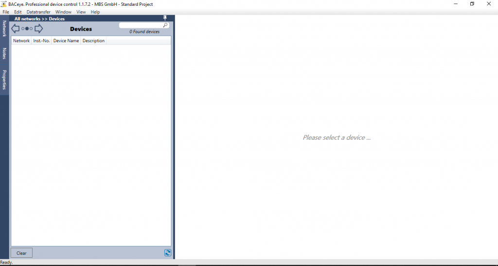
4) Next step after saving the settings is to click on the Network Tab and refresh the screen by clicking on the refresh icon displayed at the bottom of the panel next to the clear button.
After refreshing, you will get a list of BACnet Devices available on the BACnet Network.
On clicking the Specific BACnet Device that is discovered in the list, it will display the list of parameters which is supported by the respected device.
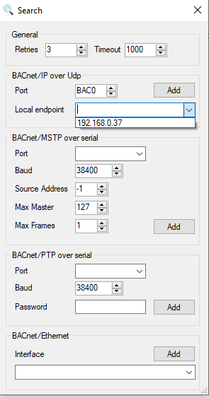
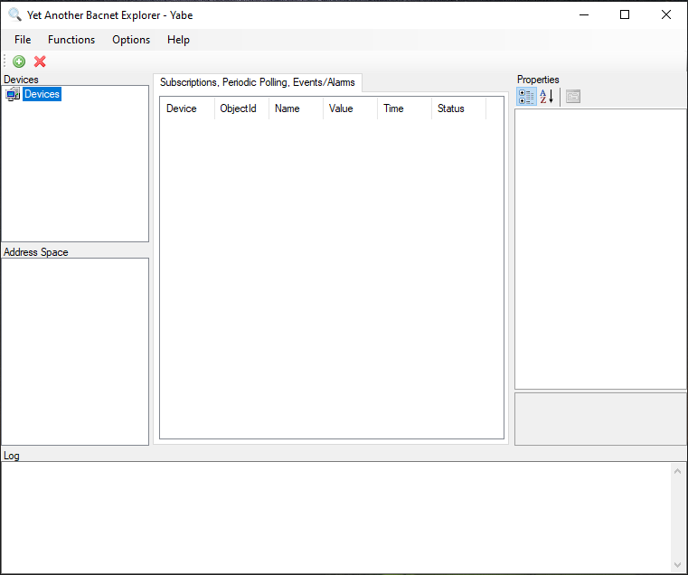
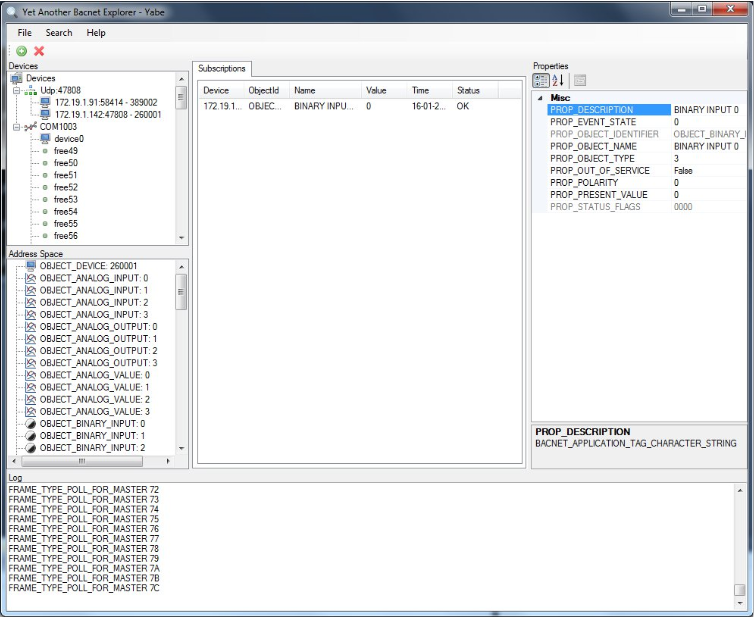
1) Start the Software and right click on the Devices.

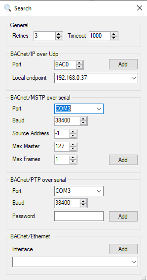
3) By adding the Device, A new window will open and select the Local End Point and Port as per your requirement.
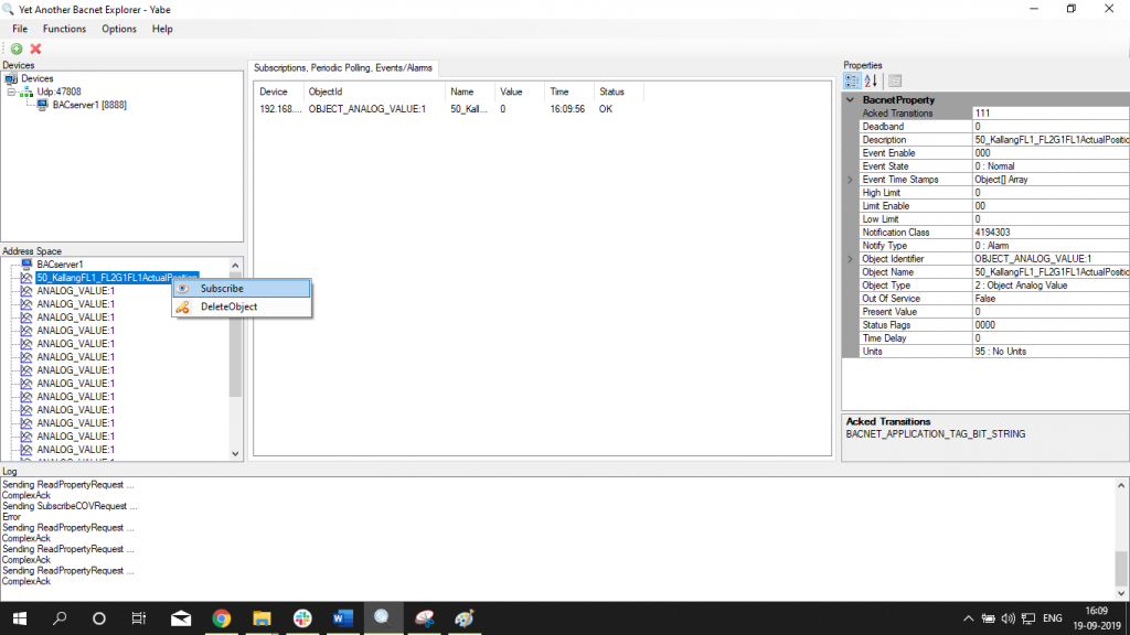
5) To monitor Live Value -> Right Click on Listed Parameter -> Click on Subscribe
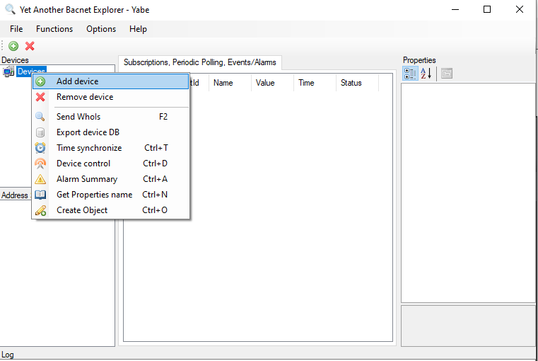
2) On right clicking the Devices, please select the Add Device option.

4) On selecting the Local End Point and Port, List of Devices will be displayed on the Device window and On clicking on the discovered device, List of the Parameters supported by the device will be discovered in the Address Space Window.
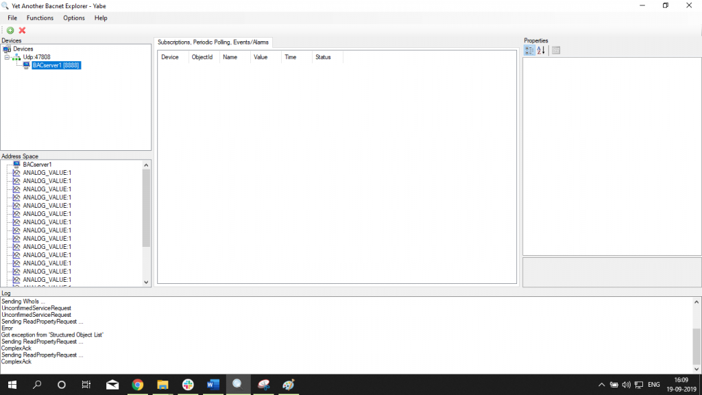
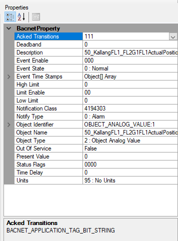
6) To view Property of the listed Parameter – > Click on the specific parameter -> BACnet Property will be displayed in the BACnet Property window displayed on the right side of the panel
Write the Value of the Parameter -> Go to Properties Tab -> Write the Value on Present Value Property and press Enter
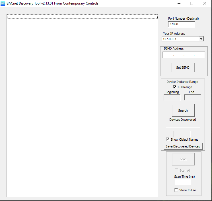
1) Start the Software, select the IP Address and click on search.
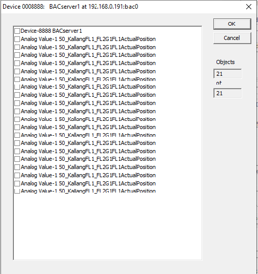
2) After adding and searching the IP Address, A new window showing Connected Device will open.
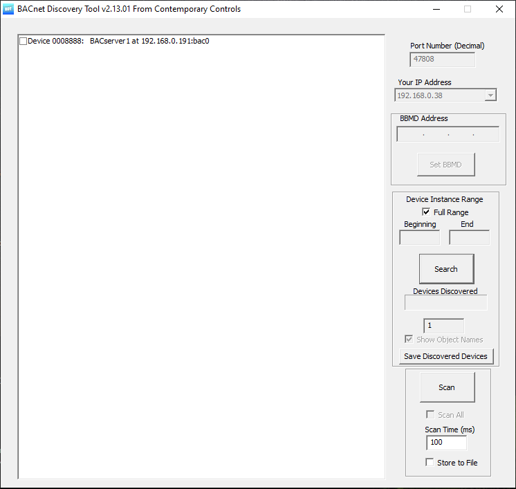
3) With the Double click on Device, a new window showing the parameters of the device will open.
1) Start the Software and right click on the Devices.
3) After Adding a device, click on the Plus (+) button which is placed below the File Menu, select a COM Port and set a required BAUD Rate.
2) On right clicking the Devices, please select the Add Device option.
4) After Selecting COM Port and Baud Rate, click on Add button placed at the end of BACnet MSTP over Serial. On clicking the Add button list of Devices will be discovered in the Address Space. On clicking the Device listed in the Address Space, Parameters of the selected device will discover under Properties Panel on the right side of the window and can view the live value in the same panel.
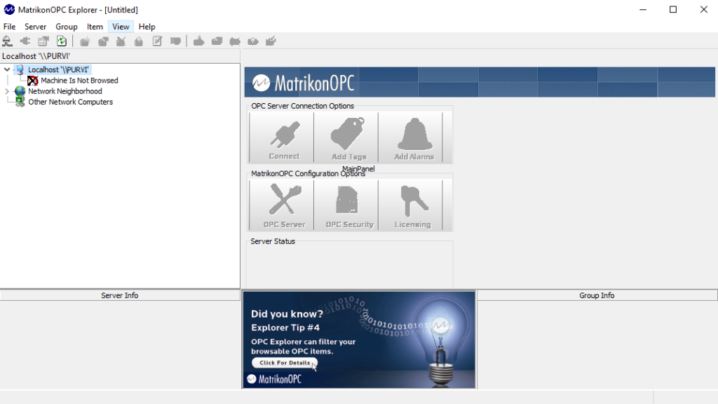
Step 1: Main Pane of the Application
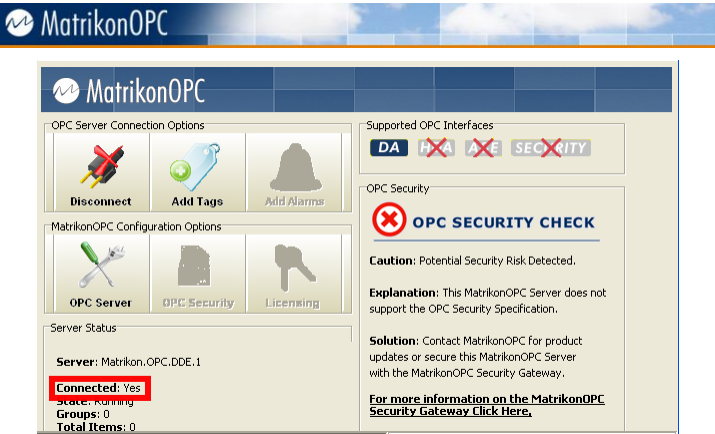
Step 3: The below screen verifies the connection between OPC server and the Application.
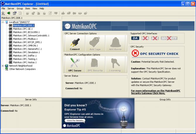
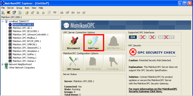
Step 2: In Navigation Pane on Left side of the screen shows listed OPC Servers installed in the local computer. Select any of the listed OPC Servers in the Navigation Pane and click on Connect button in the OPC Server Connection Options Screen section.
Step 4: You can Add tags by clicking on the Add Tags button in the OPC Server Connection Options screen section.
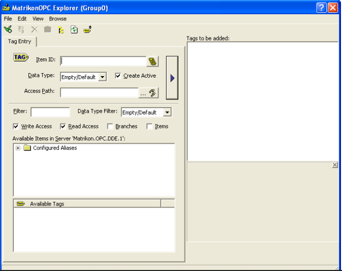
Step 5: The OPC Explorer Browsing window appears as below.
Step 6:
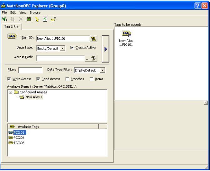
Available Items screen -> double-click mouse button on the Configured Aliases-> New Alias1 folder will be displayed.
Click on New Alias 1 folder -> Microsoft tags (FIC101,PIC204,TIC306) will be displayed in Available Tags screen section.
Double-click mouse button on FIC101 Tag displayed under Available Tags screen section -> FIC101 Tag will be displayed under Item ID Field as NEW ALIAS 1.FIC101
If the selected data point does not appear in the Tags to be Added screen, click on the right pointing arrow button to the left of this section and the data tag will appear under Tags to be added screen with a blue question mark.
Select a data tag under Tags to be added section -> click on file menu -> Click on Validate Tags Option
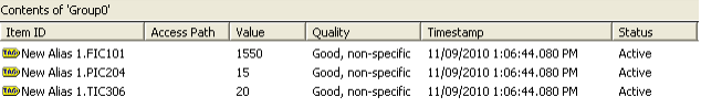
Step 7: Validate the remaining tags and close the window. An updated window showing the Active Tags will appear as below.
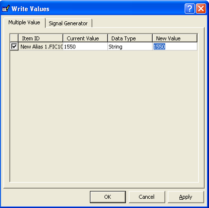
Step 8: Right Click your mouse button on FIC101 and select Write Values.
Step 9: Write Values screen appears as below. You can set a New Value by entering the value under New Value Cell.
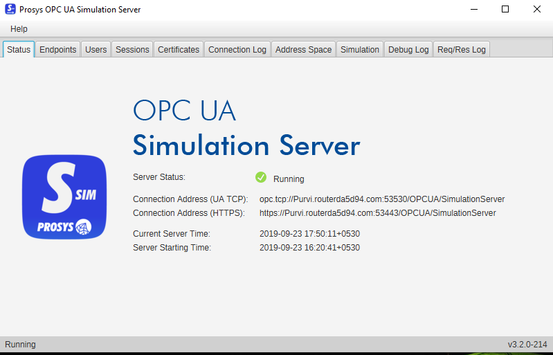
Step 1: Below image shows some basic information of the Server.
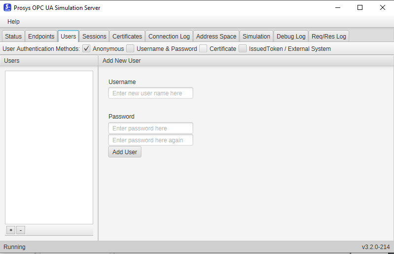
Step 3: User page displays User Authentication settings. It allows you to configure Username and Password.
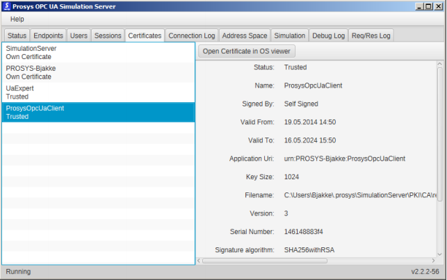
Step 5: This page let you define which application certificates you trust. When a new client application connects, its certificate will be added to the certificate list as Rejected. This can be done by right clicking the mouse button on Certificate and selecting Trust on the menu. Same can be done later to Reject a Certificate that has been Trusted Previously.
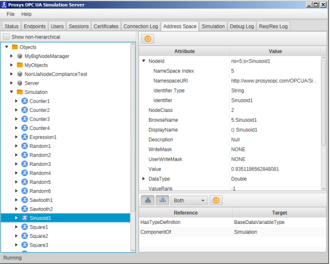
Step 7: This page is used to explore the Address Space of the server. The left part shows the Nodes in a tree view and the right-hand side shows the Attributes and References of the selected node.
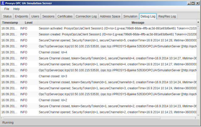
Step 9: This page shows logging from the application’s internal behavior and can be used to examine the application behavior in detail.
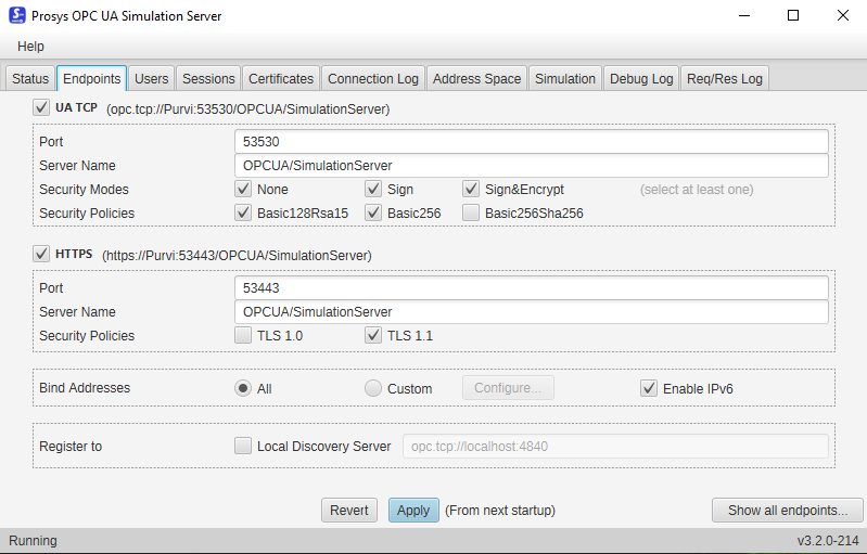
Step 2: Endpoints let you configure all endpoint related settings and view all endpoints that a server has. On clicking Show All endpoints button placed at the left bottom of the screen, a new pop up window will open displaying all the current defined endpoints.
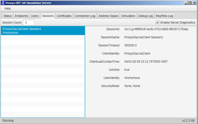
Step 4: This page displays the current session opened by the client application. On the left, the session list shows the session names and, on the right,, displays the available information about the selected session.
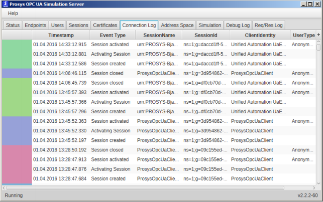
Step 6: It shows the history of Client Connections.
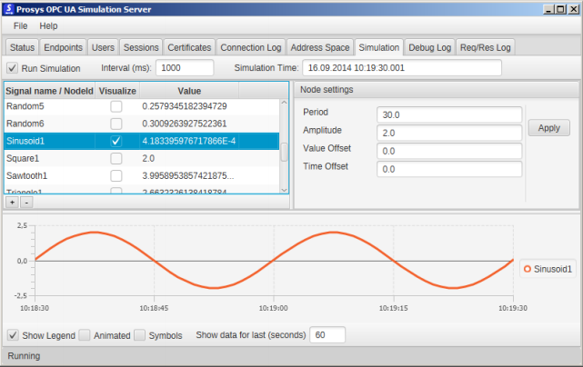
Step 8: This page allows you to configure custom signals with various simulation waveforms. Run Simulation allows you to enable/disable Simulation. Interval defines how frequently the signals are updated. Simulation Time shows the timestamp corresponding to the last update.
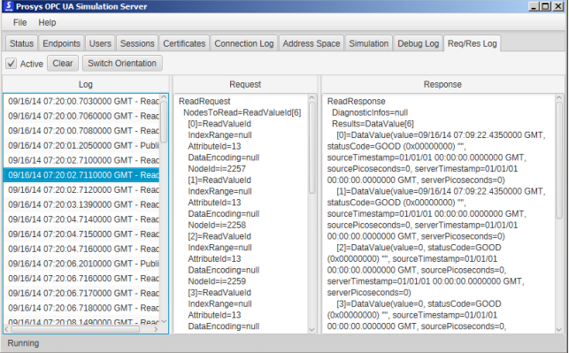
Step 10: This page allows you to record every request and response to the server apart from opening and closing of the secure channel. This feature of this application is by default and you can select the Active button to start recording.
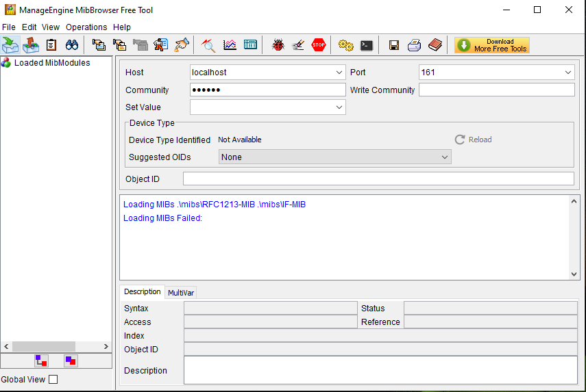
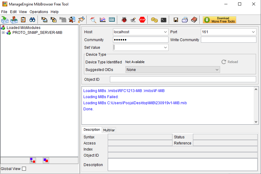
Step 1: Main Page view after Installation of the MIB Browser.
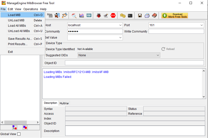
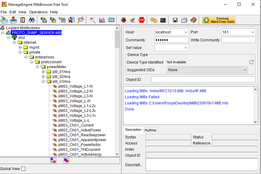
Step 3: Select the MIB file from the located path on your PC and Load the MIB file. After uploading the MIB file, a window will appear as below. You will be able to see the loaded MIB file under “Loaded MIBModbules”.
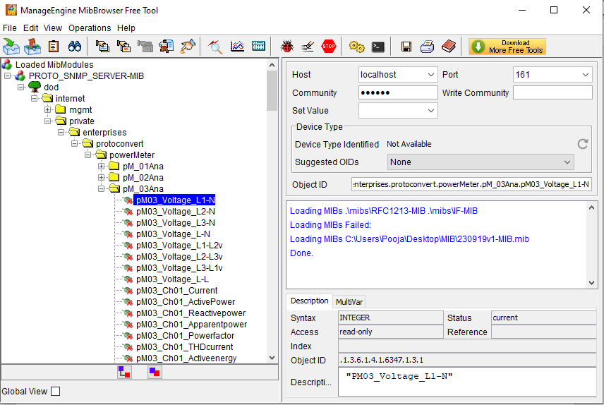
Step 5: On selecting the Parameter, you will get to see the Properties like Syntax, Access and Status under Description tab.
Step 2: Click File Menu-> Load MIB file
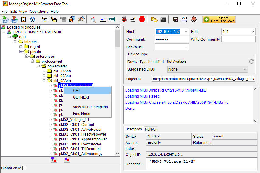
Step 4: On exploring the MIB file, you will get to see the available Parameters in the MIB File.
Step 6: Set Host IP Address, Port, Community, Write Community to GET data. To get the Value of the Parameter please right click the mouse button on any of the available Parameter.
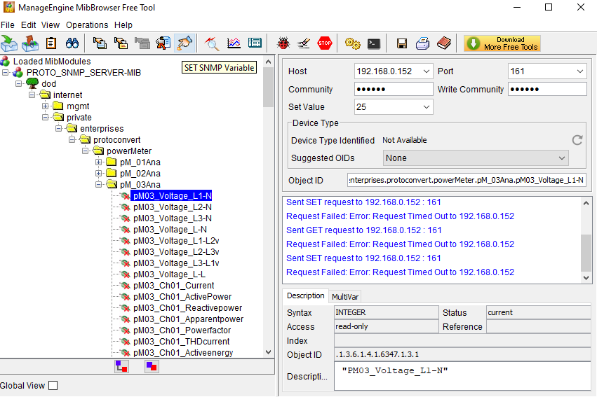
Step 7: To get the SET Value, Enter the VALUE in the SET VALUE Box then select the Parameter from the list of Parameters and click on the SET SNMP VARIABLE from the Tool Bar.
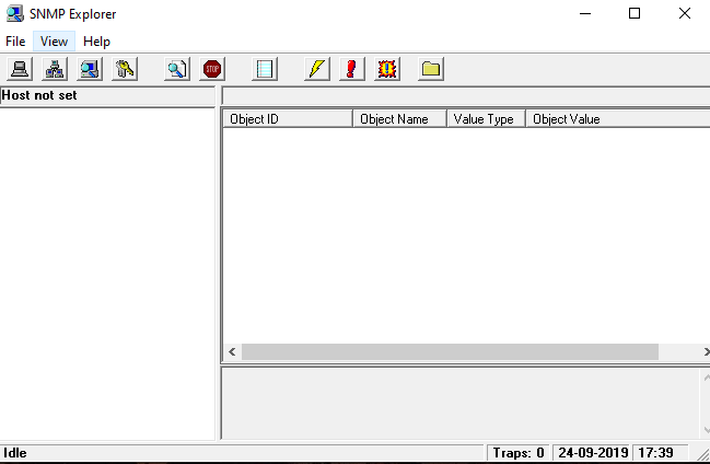
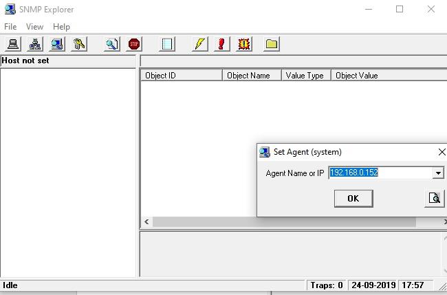
Step 1: SNMP Explorer 1.1 main page view after the Installation.
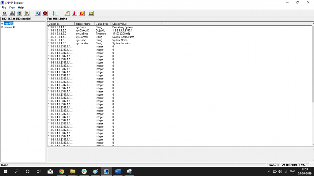
Step 3: Click on the Search button from the Tool Bar and you will get to see the MIB Discovery.
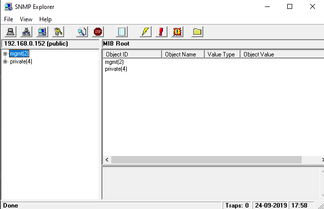
Step 2: Click on the first button which is called the SET TARGET AGENT (System) from the Tool bar and enter the Agent IP Address.
Step 4: On clicking the DISPLAY COMPLETE MIB DUMP Button from the Tool bar, you will be able to view the Full MIB Discovery in the window as shown below.
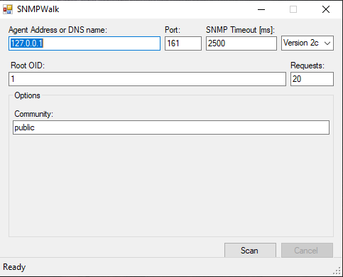
Step 1: Main Window after an Installation of an Application.
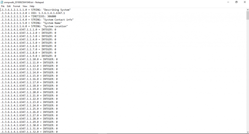
Step 3: On scanning the file, a new window will open asking to save a .txt file.
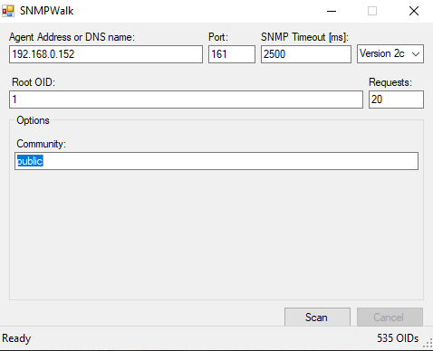
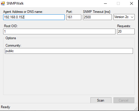
Step 2: Enter the IP Address, Port number, Community and select the Version to read the MIB File and click on SCAN.
Step 4: On saving the file, you will receive an information as shown in the below image.
Step 1. Establish a connection -> Click on Connection -> Connect -> Choose COM Port

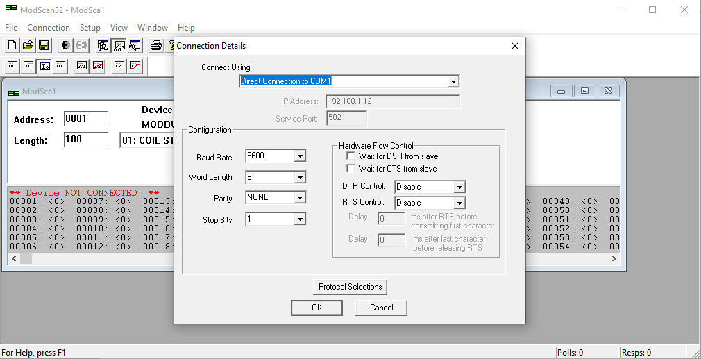
Step 2. Configuration Settings Modbus RTU -> Select Port from Connect Using -> Select Baud Rate – Word Length – Parity – Stop Bits as per Modbus Slave Device
Step 2. Configuration Settings Modbus TCP -> Select Remote Modbus TCP Server from Connect Using -> Enter an IP Address – Service Port as per Modbus Slave Device
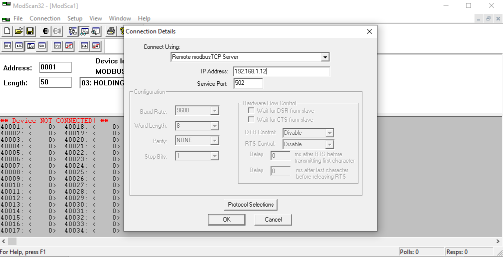
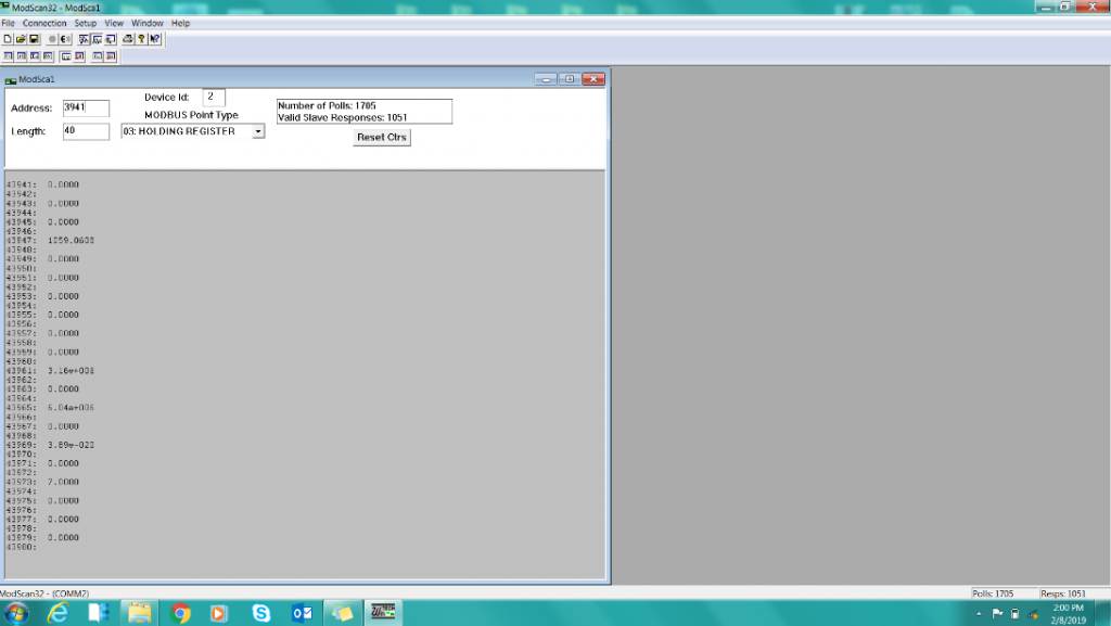
Step 3. Select Device ID – Address (of the first Modbus Register) – Length (default value 100)
As ModScan32 is put on-line, the status message “Device Not Connected” will not be displayed.
If the Status message is “Exception Response” or “Invalid Response”, it indicates that the flowmeter doesn’t understand the read command.
Modbus Registers like “Coil Status”, “Input Status”, “Holding Register”, “Input Register” are available in the menu. Please select the appropriate Register required by the Modbus Device.
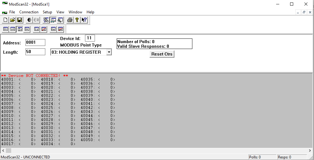
Step 4 After finishing the required Configuration Set Up, you will get a data as shown in the below Snap.